1823467-1 (1823467-1) Connector Specification & Wiring Guide
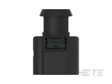
Technical engineering reference, terminal contact part numbers, wire cavity seal diameters, wedgelock secondary retention, and complete cavity pinouts for the 1823467-1 (P/N: 1823467-1) by TE Connectivity.
You can drop the 1823467-1 directly onto your harness drawing using our interactive browser-based harness CAD canvas. Wiringly automatically tracks wire gauges, cavity seals, terminal part numbers, and generates professional manufacturing cutting lists. Start Free Harness Design in Wiringly Studio
Technical Specifications & Dimensions
The 1823467-1 is an environmentally sealed Female (Receptacle / Sockets) designed to withstand extreme thermal, mechanical, and chemical stresses in high-performance automotive, commercial transport, and motorsport environments.
| Specification Parameter | Value / Technical Specification |
|---|---|
| Connector Name / Model | 1823467-1 |
| Manufacturer Part Number (MPN) | 1823467-1 |
| Manufacturer | TE Connectivity |
| Connector Category | CONNECTOR |
| Gender / Form Factor | Female (Receptacle / Sockets) |
| Number of Positions (Cavities) | 6 Contacts |
| Maximum Continuous Current | 20A |
| Housing Dimensions (W × H × L) | 25.5mm (W) × 36.4mm (H) × 27.3mm (L) |
| Ingress Protection Rating | IP67, IP68, IP69K (Submersion & high-pressure washdown) |
| Operating Temperature Range | -55°C to +125°C continuous (-67°F to +257°F) |
| Housing Material | Heavy-duty, glass-filled thermoplastic with high impact strength |
Compatible Terminals & Crimp Contacts
Choosing the correct terminal contact plating and manufacturing style is critical for harness reliability:
| Terminal Part Number | Plating / Material | Construction Style | Wire Size Range | Seal Usage (With / Without Seal) | Recommendation | Application Notes |
|---|---|---|---|---|---|---|
1241380-1 | Sn | Stamped & Formed | 0.5 - 1 mm² | 🚫 Without Seal (Unsealed) | ⭐ Preferred | AMP MCP 1.5K Receptacle Contact, 0.5-1.0 mm² (Tin) |
1241380-2 | Au | Stamped & Formed | 0.5 - 1 mm² | 🚫 Without Seal (Unsealed) | Standard | AMP MCP 1.5K Receptacle Contact, 0.5-1.0 mm² (Gold) |
1241380-3 | Ag | Stamped & Formed | 0.5 - 1 mm² | 🚫 Without Seal (Unsealed) | Standard | AMP MCP 1.5K Receptacle Contact, 0.5-1.0 mm² (Silver) |
1241372-1 | Sn | Stamped & Formed | 0.2 - 0.5 mm² | 🚫 Without Seal (Unsealed) | ⭐ Preferred | AMP MCP 1.5K Receptacle Contact, 0.2-0.5 mm² (Tin) |
1418884-1 | Sn | Stamped & Formed | 0.5 - 1 mm² | 💧 With Seal (SWS) | Standard | AMP MCP 1.5K SWS Receptacle Contact, 0.5-1.0 mm² (Tin, With Single Wire Seal) |
1418884-3 | Ag | Stamped & Formed | 0.5 - 1 mm² | 💧 With Seal (SWS) | Standard | AMP MCP 1.5K SWS Receptacle Contact, 0.5-1.0 mm² (Silver, With Single Wire Seal) |
Terminal Seal Compatibility (With Seal vs. Without Seal)
This connector supports both sealed (SWS) and unsealed terminal contacts depending on your application requirements:
- 💧 Meant to be Used WITH Seal (SWS):
1418884-1,1418884-3— Crimp barrel is designed to crimp directly onto the silicone Single Wire Seal (SWS) neck for IP67/IP68/IP69K waterproofing. - 🚫 Meant to be Used WITHOUT Seal (Unsealed):
1241380-1,1241380-2,1241380-3,1241372-1— Standard/Clean Body insulation crimp barrel intended for use without individual wire seals (if selected as preferred in Wiringly, cavity wire seals are automatically omitted from your project BOM).
Contact Metallurgy & Plating Guide
- Gold Plating (Au): Unmatched resistance to atmospheric oxidation, fretting corrosion, and micro-motion degradation. Imperative for millivolt sensor circuits (knock sensors, Hall-effect crank triggers, wideband lambda) and differential CAN-Bus / LIN communications.
- Nickel Plating (Ni): High mechanical durability and excellent resistance to contact wear during frequent mating cycles. Standard for chassis switching, solenoids, and automotive accessories.
- Tin Plating (Sn): Suitable for cost-sensitive, steady-state DC power delivery (coils, electric fans, lighting), provided high contact normal force is maintained to avoid fretting.
- Solid (Machined) vs. Stamped & Formed (S&F):
- Solid Machined Terminals: Preferred in motorsport and aerospace for exceptional tensile pull strength under heavy vibration. Crimped using 4-indent / 8-indent hand crimp tools (e.g. HDT-48-00).
- Stamped & Formed Terminals: Ideal for production harness assembly and automated reel feeding using standard B-crimp tooling.
Cavity Wire Seals & Insulation Matching
Waterproofing depends on maintaining a uniform seal around the wire insulation:
| Seal Part Number | Wire Insulation OD Range | Material Composition | Ingress Protection Rating |
|---|---|---|---|
964971-1 | 1.4mm - 1.9mm | High-Grade Silicone / Fluorosilicone | IP67 / IP68 Submersion |
964972-1 | 1.9mm - 2.4mm | High-Grade Silicone / Fluorosilicone | IP67 / IP68 Submersion |
Engineering Tip: When using thin-wall high-performance motorsport wire such as Raychem Spec 55 (MIL-W-22759/32) or TXL, verify that the wire outer diameter falls strictly within the seal's minimum specification to avoid capillary water ingress.
Cavity Sealing Plugs (Blind Plugs)
Any unpopulated terminal cavities must be sealed to maintain submersible IP67/IP68 environmental protection:
| Cavity Plug Part Number | Function | Material | Installation Tip |
|---|---|---|---|
963530-1 | Unpopulated Cavity Seal | Thermoplastic / Silicone | Insert with tapered end forward until flush |
- Always install sealing plugs with the flared flange oriented outward towards the wire entry face.
- Push the plug until it rests flush against the rear grommet shoulder.
Cavity Pinout & Wiring Assignment Table
Default circuit assignments and recommended wire gauges for the 1823467-1:
| Cavity / Pin | Default Designation | Recommended Wire Gauge | Terminal Seal Usage | Compatible Circuit Types |
|---|---|---|---|---|
| 1 | Cavity 1 Circuit | 0.5 - 1.5 mm² (20-16 AWG) | 💧 With Seal (SWS) / 🚫 Without Seal | Analog Sensor, Switched 12V, or CAN Signal |
| 2 | Cavity 2 Circuit | 0.5 - 1.5 mm² (20-16 AWG) | 💧 With Seal (SWS) / 🚫 Without Seal | Analog Sensor, Switched 12V, or CAN Signal |
| 3 | Cavity 3 Circuit | 0.5 - 1.5 mm² (20-16 AWG) | 💧 With Seal (SWS) / 🚫 Without Seal | Analog Sensor, Switched 12V, or CAN Signal |
| 4 | Cavity 4 Circuit | 0.5 - 1.5 mm² (20-16 AWG) | 💧 With Seal (SWS) / 🚫 Without Seal | Analog Sensor, Switched 12V, or CAN Signal |
| 5 | Cavity 5 Circuit | 0.5 - 1.5 mm² (20-16 AWG) | 💧 With Seal (SWS) / 🚫 Without Seal | Analog Sensor, Switched 12V, or CAN Signal |
| 6 | Cavity 6 Circuit | 0.5 - 1.5 mm² (20-16 AWG) | 💧 With Seal (SWS) / 🚫 Without Seal | Analog Sensor, Switched 12V, or CAN Signal |
Harness Assembly & Crimping Best Practices
- Wire Stripping: Strip wire insulation cleanly (recommended 5.0mm – 6.5mm) without nicking or severing individual copper strands.
- Crimp Height Verification: Verify crimp height and terminal pull-out force using a certified calibrated crimper and micrometer.
- Terminal Insertion: Push contacts through the rear elastomeric grommet until an audible tactile click indicates positive retention.
- Secondary Lock Installation: Slide the wedgelock into the front face until it locks flush with the connector housing.
- Service & De-pinning: If de-pinning is required, remove the wedgelock with a hooked removal tool, then gently release the internal plastic retaining finger with a small flat blade screwdriver while pulling the wire from the rear.
Design Your Harness with Wiringly CAD
Wiringly makes creating professional, error-free wiring diagrams and harnesses fast and accessible. Drop the 1823467-1 directly onto your schematic canvas, route multi-conductor twisted pairs, auto-generate connector pin tables, and export accurate cutting lists.
- Explore our Connector Directory to compare other connector series and pin counts.
- Learn how to import parts from TE Connectivity in the TE Connectivity Import Guide.
- Learn how to create custom connectors in the Creating Custom Connectors Guide.
- Learn how to manage wire bundles and heat-shrink in the Wire Management Guide.
- Jump right into building with the Wiringly Quick Start Guide.