Printing & Exporting
The goal of all this design work is to get the data you need to actually build the harness. Wiringly provides multiple ways to get your design out of the browser and into the real world: Generating a Formboard for manufacturing and Exporting PDF/Tables for documentation.
[!TIP] This Chapter 5 walkthrough demonstrates the final stage of the process: generating a 1:1 scale manufacturing drawing and automated wiring/BOM reports.
1. Generate Formboard (Manufacturing)
This feature is designed specifically for the physical construction of the wire harness. It creates a 1:1 scale image that is intended to be printed, taped to a workbench, and used as a template to lay out your wires. You don't need to measure twice and cut once—just lay your wires directly on top of the drawing.
Key Features
- 1:1 Scale: The output is dimensionally accurate. A 100mm section of wire on the screen will measure exactly 100mm on the paper.
- Construction Focused: Components are rendered with their stylized representations to aid in layout.
- Zoom Independent: The system captures the entire design, regardless of your current zoom level or viewport position. You don't need to worry about "fitting" it on the screen before printing.
How to Print
-
Navigate to the Canvas view.
-
Click the Generate Formboard button.
-
Choose your settings:
- Paper Size: Select from standard paper sizes (A4, A3, letter, etc.) depending on your printer capabilities.
- Strategy: Choose Tiled Pages to divide the formboard across multiple standard sheets, or select Single Sheet (Roll) if you are using a roll plotter for a continuous, seamless print.
-
Click Start Print.
-
Click Start Print.
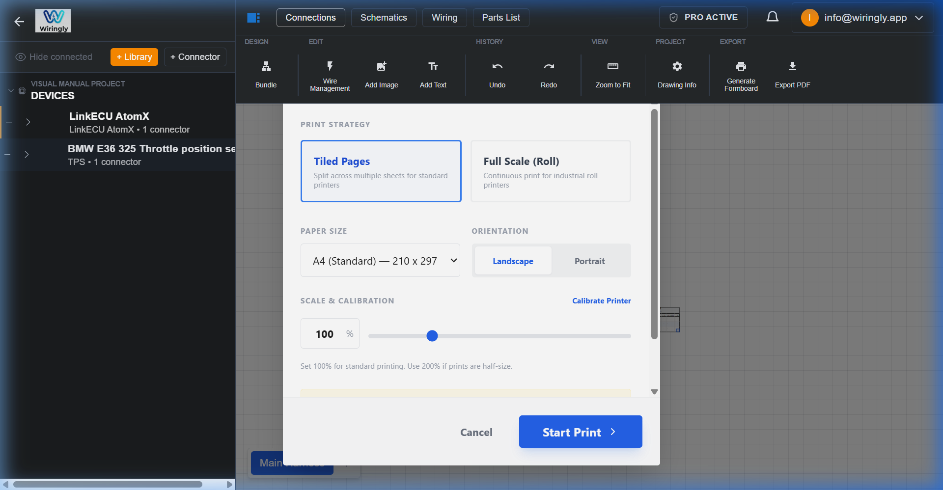 Automated 1:1 Scale Formboard export with tiling and roll options.
2. Printer Calibration
Since every printer and browser combination can handle scaling slightly differently, Wiringly includes a calibration tool to ensure your 1:1 prints are perfect.
When to Calibrate
- If your printed lines are shorter or longer than expected.
- If you change printers or computers.
- Note: Your calibration setting is saved automatically to your browser, so you only need to do this once per setup.
Step-by-Step Calibration
- Open the Generate Formboard dialog.
- Click the Calibrate Printer link.
- Click Print 100mm Test Sheet.
- Take the printed page and measure the test lines with a ruler.
- Enter the measured value (e.g., if it measured 48mm, enter
48). - Click Auto-Calibrate.
The system will calculate a compensation scale (e.g., 208%) and apply it to all future prints.
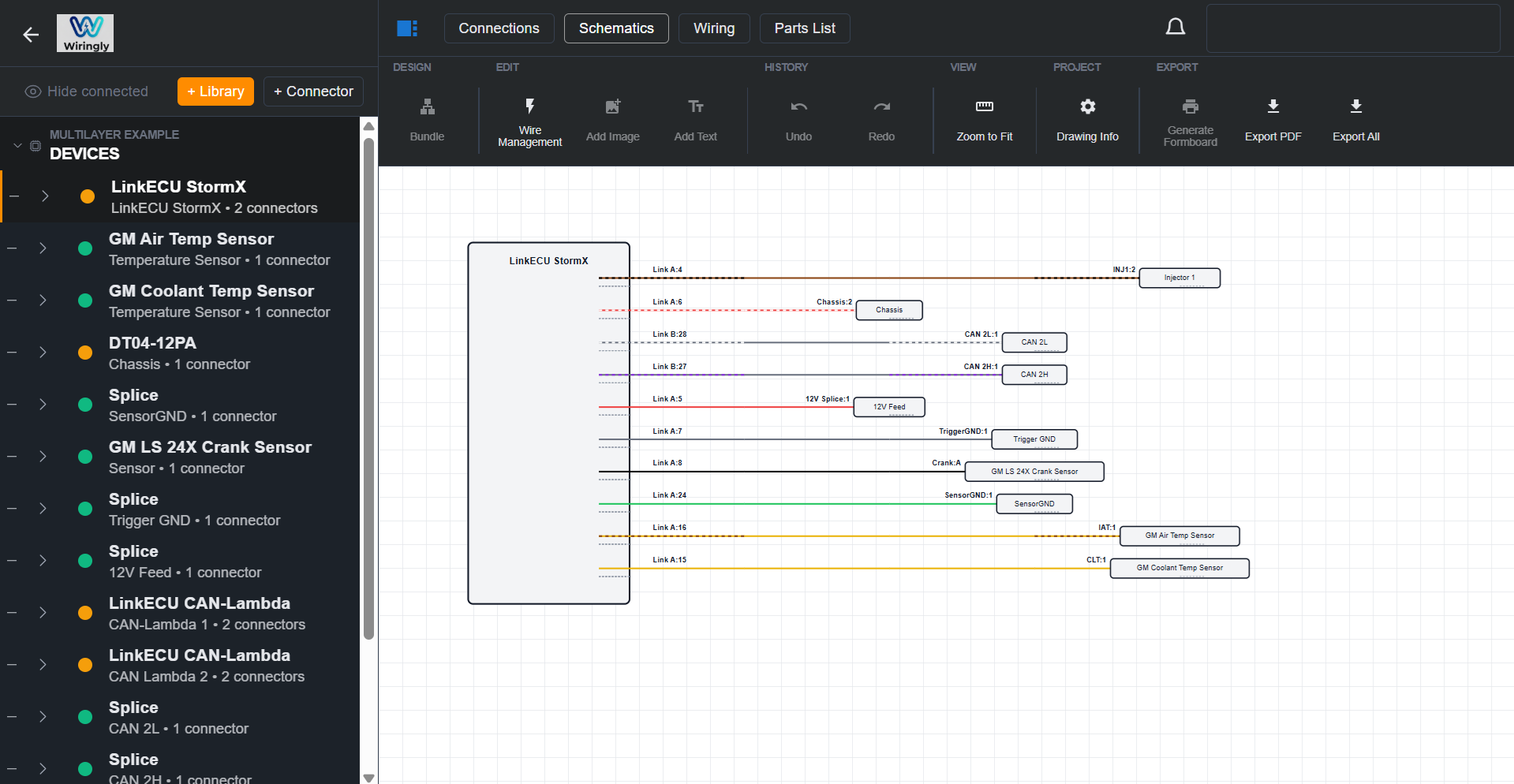
3. Schematic View
Your schematics build themselves as you connect things on the canvas. If you change a connection on the canvas, the schematic updates automatically. It’s a great way to verify the logic of your design without getting bogged down in the physical routing.
4. Wire Tables
The Wiring List tab shows every connection in your harness from both perspectives (source and destination), along with wire color, gauge, and cut length.
At the top of the table you'll find a Length Adjustment toolbar that lets you add real-world cutting margins before you print or export. All lengths are automatically rounded up to the nearest 10 mm so you never have an awkward 361 mm cut — it becomes 370 mm.
See the Wiring List — Length Adjustments page for a full explanation of each setting.
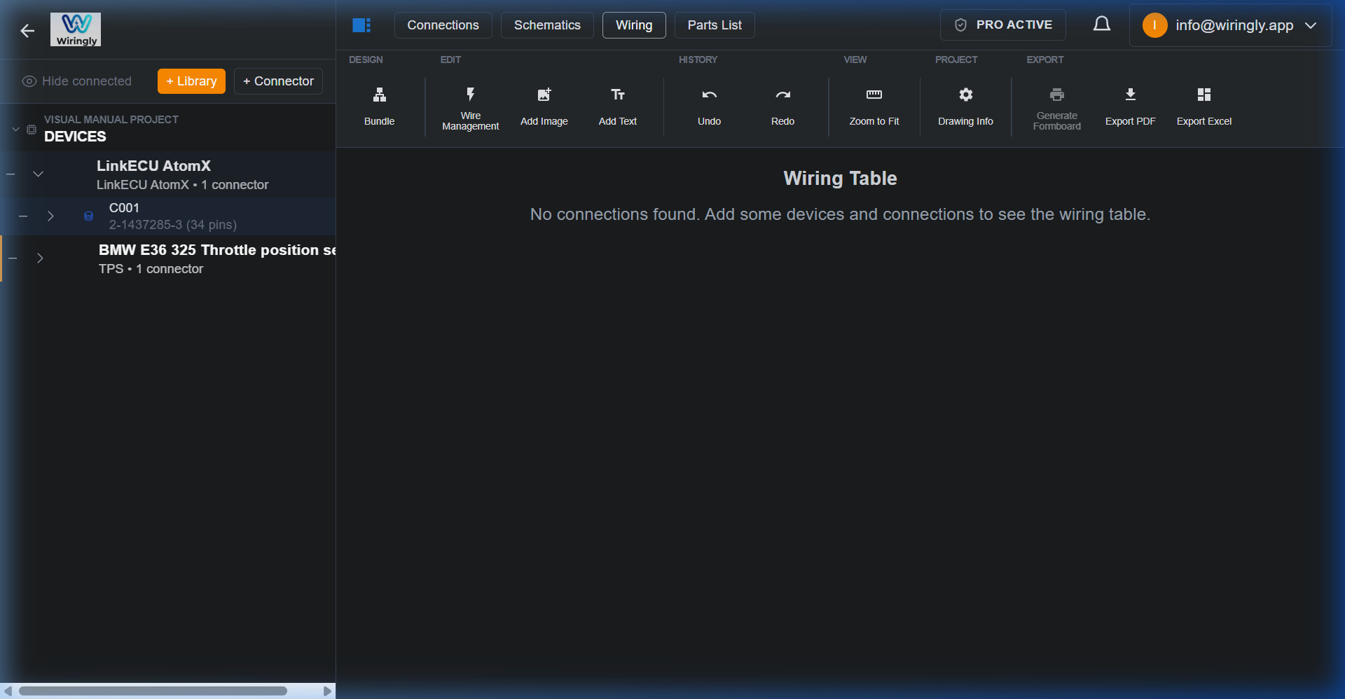 Automated Wiring Table with length adjustments applied.
5. Parts List (BOM)
- Custom parts you've added to component properties.
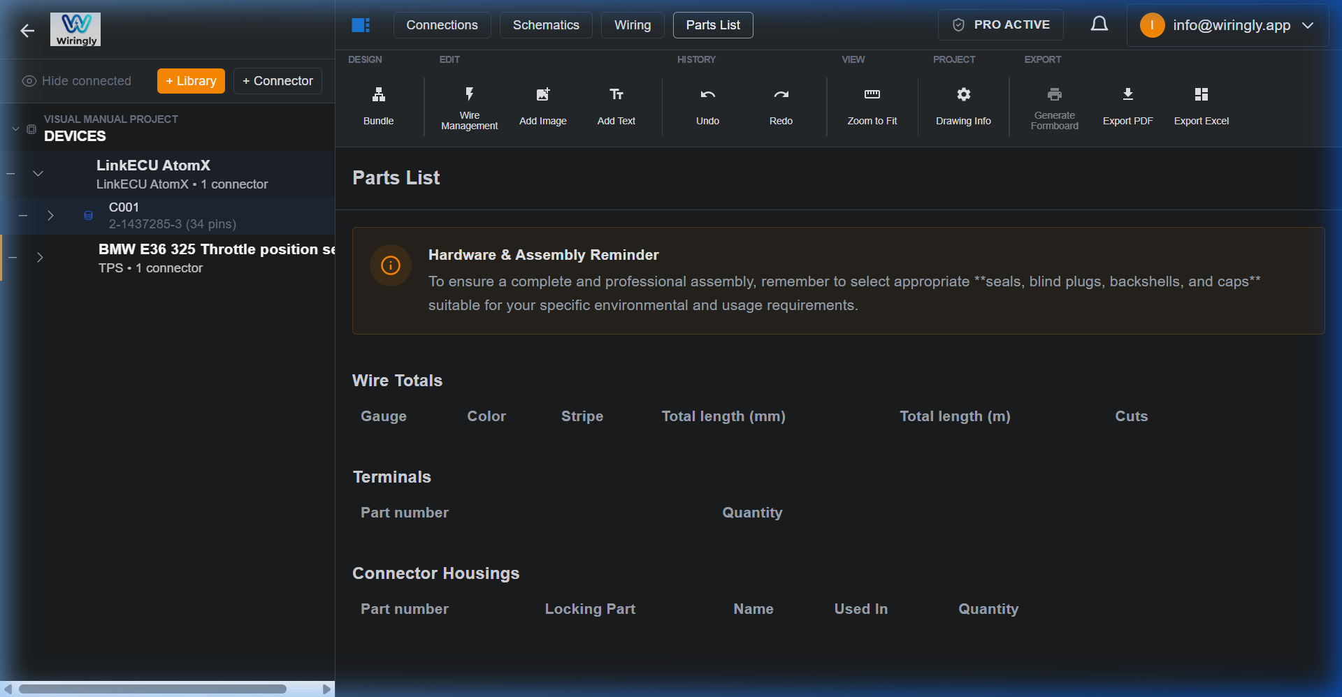 Automated Bill of Materials (BOM) with assembly reminders.
[!WARNING] Always double-check the BOM before placing a huge order! It’s a tool to help you start your shopping list, not a final authority.