The Device Tree
The Device Tree is the primary navigation and management tool in Wiringly. Located on the left side of the interface, it provides a hierarchical view of your entire harness project.
Overview
Think of the Device Tree as your project's inventory manager. It shows every component you've added to the design, both components and connectors.
Key Features
-
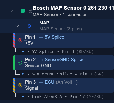
Hierarchical View: Devices are the top-level items. Expanding a device reveals its connectors, and expanding a connector reveals its individual pins.
-
Status Indicators: Visual cues help you see which pins are connected and which are still open.
Adding Components
There are two primary ways to add items to your project using the buttons at the top of the Device Tree:
1. + Library
Opens the Component Library. Use this to add pre-defined components like ECUs, Sensors, and Actuators.
- Search: Find parts by name or category.
- Select: Clicking a card immediately adds that device to your tree.
2. + Connector
Adds a Standalone Connector. Use this for inline connectors, bulkheads, or any connector that isn't part of a specific device.
- Admin made connector: Select from common connector types (e.g., DT, DTM, Superseal) that's already saved in connector library
- Create a connector: Build a connector with all the information and it will be added to your connector library for future use. Like in component library, we recommend to take your time filling out the information. It will benefit you in the long run. And it's not too difficult to do properly once.
Managing Devices
Right-clicking on any item in the tree opens a context menu with actions specific to that item:
| Level | Context Menu Actions |
|---|---|
| Device | Edit Device: Change component specifications (e.g. renaming or tweaking part numbers). Edit Description: Change component description. Duplicate: Create a duplicate of the device. Delete: Remove device and all its connections. |
| Connector | Edit Connector: Change connector specifications or pin layout. Replace Connector: Swap the connector model with another from the library. Duplicate: Create a duplicate of the connector. Delete: Remove the connector and all its connections. |
| Pin | Edit Description: Add or edit pin signal description. Quick Connect: Connect this pin to another pin on the canvas. |
Hiding Completed Items
The "Hide connected" toggle at the top of the tree allows you to filter out devices that are fully wired. This is extremely useful for focusing on remaining work in large projects.
Design Workflow Tips
- Populate Control Units First: Starting with control units (ECU or PDM) is usually best. Wiringly collects suggested wire colors and pin labels directly from control unit definitions. Next, add sensors and actuators in the general direction where they will be positioned on the canvas. Make connections, then specify line lengths.
- Use the Tree for Navigation: Clicking any pin or connector in the tree immediately highlights and centers it on the canvas, making it easy to trace specific signals across complex harness designs.
- Connector Naming Strategy:
- By default, connectors are auto-named sequentially (e.g.
C001,C002). - Pro Tip: Rename these to clear, functional identifiers such as
AtomX A,CLT,IAT, orFirewall_Main. Meaningful connector names make selecting target pins in the Wiring Table or Schematic views significantly faster.
- By default, connectors are auto-named sequentially (e.g.